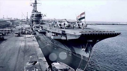
vertical weather profiles - Experiments on board INS VIKRANT
(Aircraft Carrier warship of India) & Gaveshnai (Research ship of NIO, Government of India)
DIRECTOR
CINEMATOGRAPHER
SOUND
CLIENT
YEAR
Alexander Thompson
Isabella Martinez
Isabella Martinez
Isabella Martinez
2024
OVERVIEW
Significantly installed and experimented an onboard system INS VIKRANT for gathering vertical wind profile over sea surface for ‘Guidance Parameter’ to Missiles.
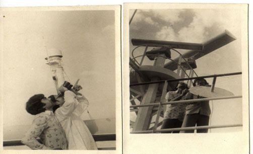
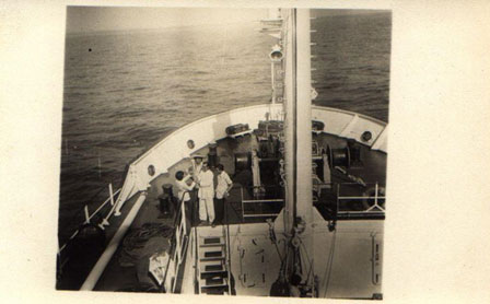
This was an international project to find out vertical weather profiles (Wind speed, wind direction, air pressure, humidity and temperature) over the Indian Ocean (from surface to upper atmosphere upto 20 km vertical and 80 to 100 km horizontal distance from the location of balloon launching). System was installed on board INS Vikrant, Gaveshana and other naval ships. The ships were cruising in the Arabian sea for about two year. I actively participated in Design/ Development, Installations and worked on board ‘INS Vikrant’ and other Government research vessels for Monsool Experimentations.
CHALLENGES & APPROACH
A system was installed and experimented on board INS VIKRANT for gathering vertical wind profiles over sea surface for ‘Guidance Parameter’ to Missiles.
THE RESULT
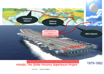
For prediction of the global monsoon, upper air movement and the vapor evaporation in Arabian sea is considered as a very important aspect for the meteorological departments. Upper-air winds are generally computed by converting the displacement of a balloon-borne target into horizontal components. The position of the balloon-borne target with reference to the horizontal plane is computed from angles and distances measured either visually or electronically by a stationary, stable, surface-mounted tracking device. Use of the Omega navigation system to locate the balloon-borne target eliminates the need for the surface-based tracking system to be either stationary or stable. The Omega navigational system stations (Omega stations) transmit on common frequencies, 10.2, 11.33, and 13.6 kHz, with precise control of frequency and phase in a fixed sequence each 10 sec. The low frequency, high power transmissions will provide global coverage with only 8 transmitters. Currently, the North Dakota Omega station is already transmitting at full power, 10 kW, but the Norway, Trinidad, and Hawaii stations are as yet transmitting at about 1 kW. The signal phase difference between two Omega stations as received by the 13.6 kHz receiver in the radio sonde determines the hyperbolic line of position (LOP) of the balloon in the horizontal plane The signal phase difference between another pair of transmitting stations (which may include one previously used station) establishes a second line of position. The inter a section of these two lines of position fixes the location of the balloon on the horizontal plane relative to the family of LOP’s of the system. Subsequent position-fixes establish the displacement over a period of time. Wind speed and direction were computed from the phase difference of the omega signals received from different stations to a particular point on the upper space, where the balloon is present at a particular time. The location on the ground is pre-fed in the oftware at the time of launching the balloon, since the phase differences of these station pairs do not provide a unique solution to the location problem. The unique solution is obtained by computing LOP’s of the balloon launch point and accumulating lane crossing with the reference latitude and longitude entered as reference location.
Above image shows the “Master System Diagram” showing the ‘floating balloon, Omega upside wireless links. The system was supported by a very powerful ‘electronic system’ having RF sub-system, telegraphic interface, Modems, Analog and Digital signal processing sub-systems developed by ISRO. The descending radiosonde system was developed based on the customised radio radiosonde developed for upper air observations.